
Installing a ASCO SCG353A047 valve correctly is crucial for the efficiency and longevity of your dust collection system. A proper installation ensures optimal pulse-jet cleaning, prevents costly air leaks, and minimizes downtime. This guide will walk you through every critical step, from preparation to final testing, helping you execute a flawless setup.
1. Safety First: System Isolation and Preparation
Before touching any part of the system, safety is paramount. Incorrect installation can lead to equipment damage or personal injury.
Shut Off and Lock Out
Begin by completely shutting off the compressed air supply to the dust collector. Use a lockout/tagout procedure on the electrical power source to ensure the system cannot be accidentally energized while you are working .
Depressurize the Manifold
Even after shutting off the main air supply, residual pressure often remains trapped in the manifold. Vent this pressure completely. Attempting to remove a valve from a pressurized line is dangerous and can cause the valve to become a projectile .
2. Pre-Installation Checks
Taking a few minutes to prepare and inspect will save you significant time troubleshooting later.
Verify the Model
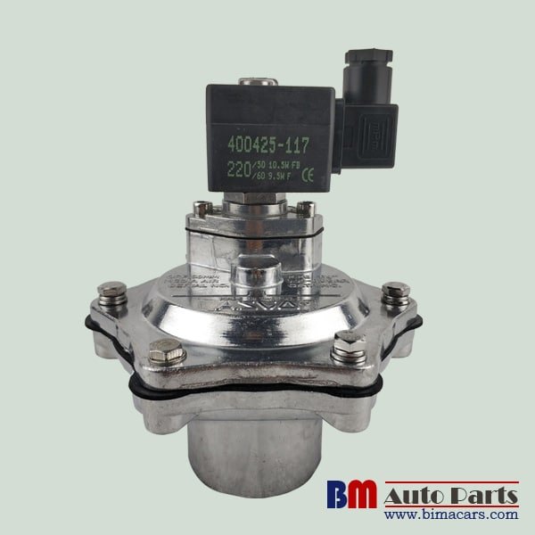
Confirm that your replacement or new ASCO SCG353A047 valve matches the required specifications. Check the voltage (e.g., 24V DC, 120V AC) and the interface size (typically 1″ NPT) against your system’s requirements . The SCG353A047 is commonly used in industrial dust collection systems .
Inspect the Valve and Manifold
Examine the new valve for any signs of shipping damage. Look inside the valve body and the manifold port to ensure they are free of debris, rust, or old thread sealant. Contaminants are a leading cause of valve failure, as they can block the pilot orifice or prevent the diaphragm from seating correctly .
- Alt Text: A technician inspecting an ASCO SCG353A047 valve and manifold port for debris before installation.
3. Applying Sealant Correctly
Proper sealing is essential to prevent air leaks, which reduce system efficiency and increase energy costs.
Use Teflon Tape or Sealant
Apply a suitable sealant to the male threads of the valve. If using PTFE (Teflon) tape, wrap it clockwise around the threads when looking at the valve from the end. This prevents the tape from unraveling as you screw the valve in .
Avoid Overtightening
Hand-tighten the valve into the manifold first, then use a wrench to give it an additional 1/4 to 1/2 turn. Overtightening can stress and crack the valve body. Ensure the valve is oriented correctly so the solenoid coil is easily accessible and properly positioned (usually vertical) .
4. Electrical Connections
Connecting the solenoid correctly is critical for reliable operation and safety.
Verify Power Supply
Double-check that the power supply matches the voltage and frequency specified on the ASCO SCG353A047 valve coil. Applying the wrong voltage can instantly burn out the coil .
Wire the Solenoid
The SCG353A047 typically uses a standard DIN 43650 connector . Remove the connector cover and connect the power leads. Ensure the ground wire is properly connected. If the connector has an LED light, ensure the polarity is correct for DC voltages, or it may not illuminate . Tighten the fixing screw to hold the connector firmly onto the solenoid.
- Alt Text: Close-up of wiring a DIN 43650 connector for an ASCO SCG353A047 solenoid valve.
5. Positioning and Orientation
The physical orientation of the valve affects its performance and lifespan.
Mount the Valve
For pulse-jet applications like the SCG353A047, the valve is often mounted directly onto the air manifold. Ensure the gasket or O-ring (if applicable) is seated correctly before securing any mounting bolts. The valve body should be supported and not hanging solely by the pipe threads .
Coil Orientation
While many valves can operate in any orientation, it is considered best practice to mount the valve with the solenoid coil upright or horizontally, but not inverted, to prevent condensate from pooling inside the coil housing .
6. Manual Testing Before Power-Up
Before restoring full power and air pressure, perform a basic manual test.
Check for Free Movement
Many ASCO pulse valves include a manual operator. With the air supply still off, press the manual operator. You should feel the valve click or actuate internally. This confirms the mechanical parts move freely and are not stuck .
Restore Air Gradually
Slowly turn on the main air supply while listening for immediate leaks around the new valve’s threads and body.
7. Final Electrical and Functional Test
Now it is time to fully integrate the valve into your system.
Power On and Test
Restore power to the system and initiate a manual cleaning cycle from the dust collector controller. Listen for the sharp, distinct “pop” of the diaphragm opening, followed by a clean seal when it closes .
Leak Detection
Use a soapy water solution around the thread seal and the joint between the valve body and manifold. If you see bubbles forming, you have a leak that needs to be addressed by tightening or re-applying sealant .
- Alt Text: A technician using a soapy water spray to check for air leaks on a newly installed ASCO valve.
Conclusion: Ensuring Long-Term Performance
A successful ASCO SCG353A047 valve installation comes down to careful preparation, correct sealing, and thorough testing. By following these seven steps—isolating power, cleaning components, sealing threads properly, and verifying electrical connections—you ensure reliable operation, optimal cleaning efficiency, and extended valve life. Proper installation not only prevents immediate failures but also reduces long-term maintenance costs.
For more information on maintaining your dust collection system or to browse our full range of replacement valves and repair kits, visit our product page today.